The raytracing program POV-Ray[2, 3] was used for the examples.
The sun was set at a 3 degree horizontal and a 20 degree vertical angle from the origin by using the commands specified in figure 8.
To calculate the unit vector 〈-0.052336,0.341551,-0.938405〉 shown in figure 8, we let θ represent the vertical angle and we let φ represent the horizontal angle.
From this, the following formulas represent the unit vectors used:
|
| (1) |
 | (2) |
 | (3) |
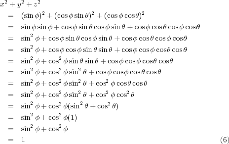
Verification that 〈x,y,z〉 is a unit vector can be accomplished with the formula
 | (4) |
Using formulas 1, 2 and 3, as well as the relationship
 | (5) |
the following computations are performed:
(Note: the hard-coding of the unit vector in figure 8 must be changed in time.)
There are extra commands available in case an area light is desired, as documented in §A.2.
If soft shadows from objects distant from, say, the ground are desired, this effect is simulated with an area light. This simulates the necessary umbra and penumbra in a manner much like the sun.
There is a plane the area lights are attached to, so to speak. To determine which way and which length the axis vectors u and v with a distance d are drawn are computed with the formulas
 | (7) |
and
 | (8) |
The commands used to do this are shown in figure 9.
|
In time, more accurate vector computation routines will be determined and used.
A picture showing a view of the “sun” approximating normal human visual angles is shown in figure 10.
This graphic is provided to check the placement and proportions of the sun. Code which generates this graphic is provided in figure 11.
|